
Giving Shape to Ideas

Optimal exploitation of different processes and multiple technologies is to be the way of fabricating metallic objects in future. To this end, IIT Bombay has developed Hybrid Layered Manufacturing, an economical Metal 3D Printing System. An integrated platform for material addition, material subtraction, stress relieving, preheating and inspection, its next two versions are also underway at IIT Bombay and IIT Guwahati. An exclusive spotlight on the cutting-edge in Metal 3D Printing…
Additive Manufacturing (AM), popularly known as 3D Printing (3DP), is an important enabler in the current 3rd Industrial Revolution. It, a divide-and-conquer strategy, helps in compressing the time-to-market through total automation in manufacturing. Its other significant benefits are direct assemblies, non-linear ducts with varying cross sections such as conformal cooling channels, lattice structuring and Functionally Gradient Matrix (FGM).
Hybrid Layered Manufacturing (HLM), developed in IIT Bombay, combines the best features of additive (cladding) and subtractive (machining) processes.
Fusion of Additive and Subtractive Manufacturing
Hybrid Layered Manufacturing (HLM), developed in IIT Bombay, combines the best features of additive (cladding) and subtractive (machining) processes. HLM proceeds in a layer-by-layer manner, same as the other AM processes. CAD model of the desired component is sliced into thin layers and a toolpath is generated for each layer. The deposition material in each layer, according to the generated toolpath, is done using a Metal Inert Gas (MIG), Tungsten Inert Gas (TIG) or Laser cladding using a 3- or 5-axis kinematics. Combining material addition and subtraction is not the only hybridization in HLM. It has evolved to incorporate hybridization of the cladding processes and kinematics in-volved. Additionally, HLM in-clude multiple technologies such as preheating, face milling, stress management, and inspection to perform effectively. These different processes and multiple technologies have been proven on the 3- and 5-axis CNC machines. This is known as Single-Station Multi-Axis HLM (SSMA-HLM). Using SSMA, following case studies were carried out at IIT Bombay :
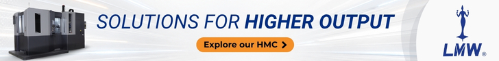
- A pair of monolithic injection molds was built for producing the egg template of Godrej refrige-rator. (See Figure 1a)
- By retrofitting the CNC machine with more than one MIG torch, a composite injection mold was produced with conformal cooling channels to efficiently produce the rear indicator body of a two wheeler. 3-axis HLM’s ability to produce triangular conformal channels was used for this purpose. (See Figure 1b)
- The third feature demon-strated by this die is adaptive discrete slicing. An Al propeller was made in two settings. (See Figure 1c)
- A complex geometry with large undercut features, ‘Impeller’ was realized by tilting the substrate appropriately on a 5-axis CNC machine. (See Figure 1d)
- The same Impeller was realized using the feature-based conformal slicing method. (See Figure 1e)
- A turbine blade was manufactured by depositing the material on both sides of the substrate. The embedded forged substrate act as a backbone of the object. The alternative deposition of layers on both sides of the substrate reduces the residual stresses from the component. (See Figure 1f)
- A tooling element (Diffuser) with conformal cooling channels was realized using H-13 tool steel material that requires an in-situ preheating up to 500°C of the prebuild layer. (See Figure 1g)
- A mounting plate of a component of a spacecraft of mild-steel and aluminum was built depositing material on both sides of the substrate (See Figure 1h). This method is similar to the one used for realizing the turbine blade.
The evolution of HLM process to use different processes and multiple technologies brings the need for a flexible manipulator such as Robotic arms for handling the different units.
Industrial Version of HLM
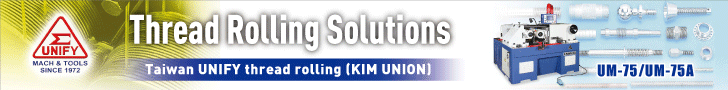
In view of the need for integrating hybrid processes and multiple technologies, we envisage the industrial version of HLM as a Multi-Station Multi-Axis HLM (MSMA-HLM) with 7 stations – MIG/TIG/Laser cladding, face milling, optical inspection and residual stress management through preheating and cold working (Figure 2). Typical sequence of operations to realize any layer is as follows :
- The carriage moves to the induction heating system at the right extreme for pre-heating the previous layer.
- It moves to the laser cladding system where the boundary loops of a few slices of fine layer thickness (say 0.5 mm) are deposited in 5-axis mode.
- It moves to the arc cladding system to fill the interior in one thick layer in 2.5-axis mode. This will be done by MIG or TIG head depending on the size of the part and precision.
- It moves to the face milling head at the right extreme for flattening the scalloped clad surface to the required height.
- It moves to the station for optical inspection where camera shoots the surface and an image processing software looks for any cracks arising out of a possible process instability such as spatter. If any crack is found larger than the pre-set permissible limit, it goes back to the face milling head where the entire recently-built layer is milled off to rebuild it again right from preheating.
- If the layer will pass the inspection, it will move to the hammering station to relieve the residual stresses.
- After the deposition of near net shape on this system, an accurate CNC machining center will be used for achieving the dimensional accuracy. This system is being fabricated through an IMPRINT project in IIT Bombay.
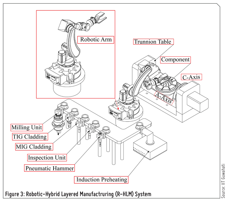
Robotic Arms in HLM
The evolution of HLM process to use different processes and multiple technologies brings the need for a flexible manipulator for handling the different units. Robotic arms are known for their flexibility of use and equipment handling with a compromise in rigidity. However, in the recent development of the robotic arms, it has been found that they can be used for milling operation as well. Robotic Hybrid Layered Manufacturing (R-HLM) (See Figure 3) system is built around a coupled multi-axis system consisted of a 6-axis robotic arm and a 2-axis trunnion table. The 6-axis robotic arm picks the appropriate unit (cladding, milling, pneumatic hammering, induction preheating or optical inspection head) from an in-line holder and perform the desirable action (adding the material, removing the material, relieving the residual stresses, preheating the prebuilt layer, or inspecting the layer) on substrate which is held on a 2-axis trunnion table. This project is under process in IIT Guwahati and focuses on understanding the build-up of residual stresses during realization of the component and ways to reduce them by optimal use of in-situ processes.
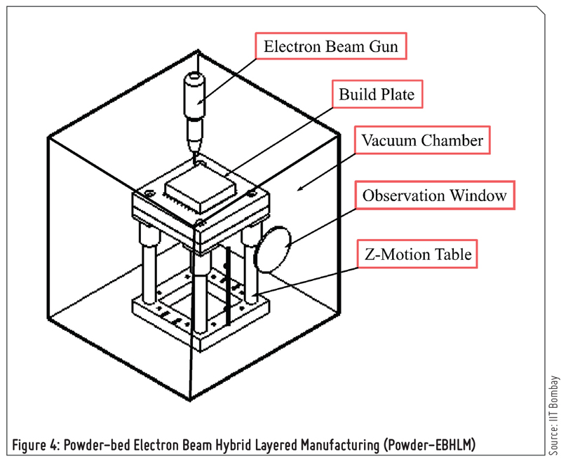
Powder-bed Electron Beam HLM
Electron Beam (EB) has several advantages such as high scanning speed, plug efficiency, compatibility with several materials and integrity (low porosities and residual stresses) due to vacuum environment which has developed its scope in AM processes. Worldwide only Arcam and Sciaky are the system providers for EB-based AM process for powder-bed and wire deposition technology respectively. IIT Bombay has UAY-2017 project on the indigenous development of powder-bed based electron beam additive manufacturing system. In this project, powder-bed technology gets hybridized with subtractive operations (see Figure 4). Need for vacuum is no longer viewed as a limitation as the benefits are more by contamination-free matrix. High energy efficiency of over 95 percent makes this a sustainable process. Its scanning speed is 1000 m/s which makes preheating the bed possible leading to the least residual stresses and distortions.
Furthermore, this permits stacking multiple parts without any connecting structures. EB will soon replace laser in all metallic applications. Its applications are more attractive in the field of medical, nuclear and aerospace where contamination and part’s integrity are the major aspects for the objects. Simultaneously, IIT Bombay has DST-2016 approved project for wire-based system too.
Software for HLM
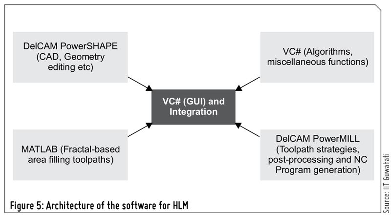
The software used for HLM process is called as Gati-Nirman. It is a Visual Studio’s Windows Forms Application (as shown in Figure 5). It is the integration of three different packages – Visual Studio, DelCAM (Autodesk), and MATLAB. Visual Studio is the programing environment. The time-tested CAD functions of DelCAM’s PowerSHAPE and the CAM functions of DelCAM’s PowerMILL are appropriately exploited. When the required functions are not available in DelCAM, either MATLAB code or VC# code are developed.
Gati-Nirman is machine independent as it can take benefit from the numerous NC post-processors available with DelCAM. All the build strategies used for the case studies done by HLM are implemented through Gati-Nirman. For example, 5-axis slicing and fractal-based area filling are the unique methods implemented in this software.
The software used for HLM process is called Gati-Nirman. It is the integration of three different packages – Visual Studio, DelCAM (Autodesk), and MATLAB.
 Facebook
 Linkedin
 Subscribe