


CONCENTRATING EXPERTISE FOR TOOL, PATTERN, AND MOLD MAKING
A collaborative project between SCHUNK, OPEN MIND, and Horn demonstrates how coordinated engineering delivers precision, productivity, and process reliability in tool and mold making. Proven technologies were combined with innovative approaches—from deformation-free magnetic workpiece clamping and high-performance milling tools to advanced CAM strategies for economical programming.
“When Uwe Weil from SCHUNK called me and told me about the idea for the project, it immediately piqued my interest. Shortly afterwards, I agreed,” says Andreas Jenter, Product Manager, Horn, whose specialty is milling with solid carbide tools.
“Clemens Bangert from the CAD/CAM manufacturer OPEN MIND also immediately agreed to the project. The hyperMILL® expert developed and programmed the 3D model of the challenging shape,” shares Weil, who is responsible for product training and technology training at SCHUNK.
“The machining process was completed in four days of intensive cooperation. One or two things may be manufactured differently in practice, but we wanted to use different approaches to demonstrate the cost-effective processing of such a demanding component,” he adds.
Magnetic Workpiece Clamping
Magnetic clamping technology is widely known in surface grinding, but it is increasingly proving its capabilities in milling applications. “There are still reservations about magnetic workpiece clamping during milling, but we wanted to use this example to demonstrate that this technology can be used and implemented reliably in production environments,” says Weil.
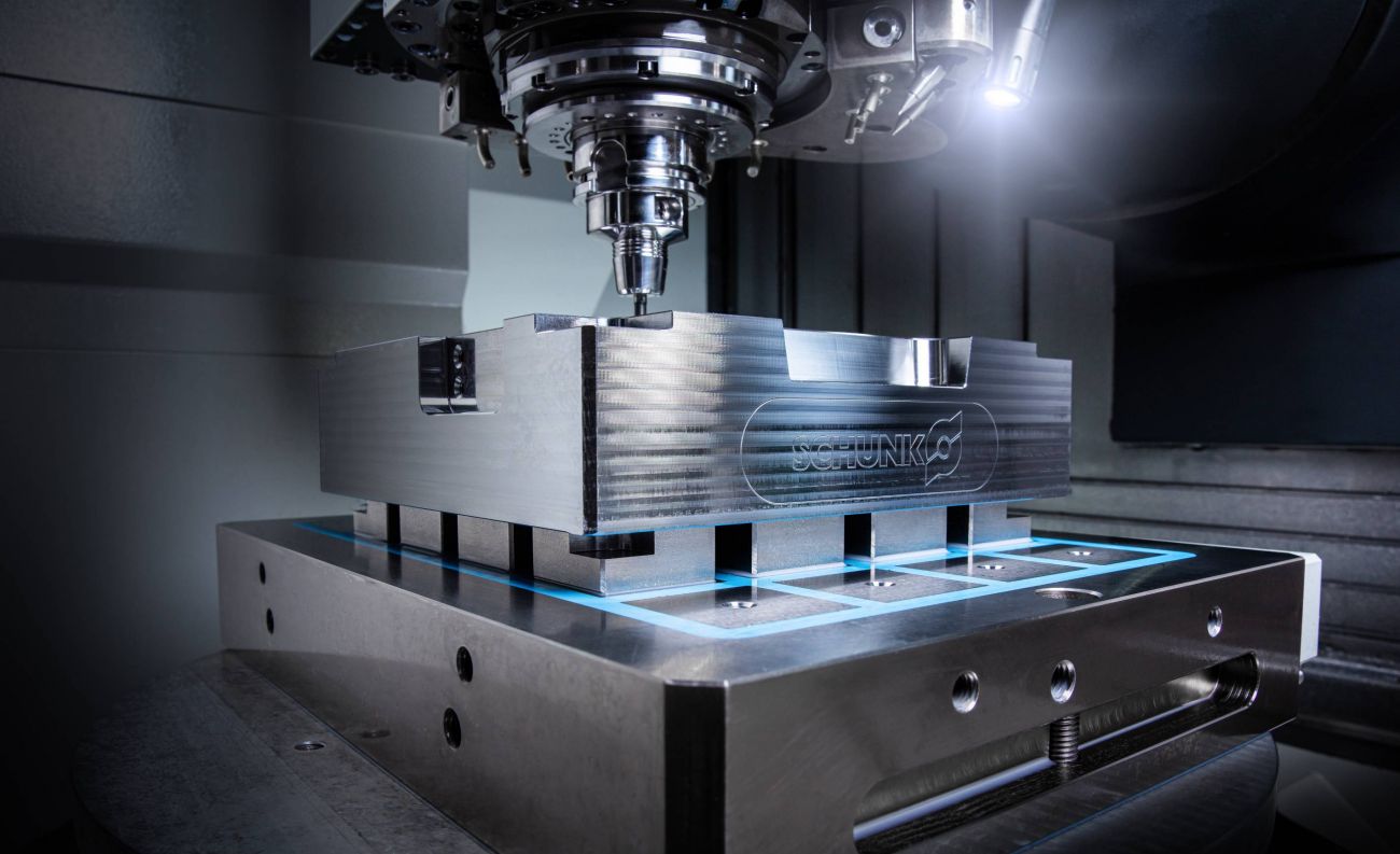
The magnetic clamping plate is connected to the SCHUNK zero-point clamping system on the machine table by means of an aluminum base plate and correspondingly arranged zero-point clamping bolts.
The magnetic tension of the blank is deformation-free. This is achieved on the one hand by fixed pole extensions for height positioning of the workpiece and on the other hand by mobile pole extensions. The mobile pole extensions adapt to the unevenness of the surface of the component. This means that the blank is not warped during clamping.
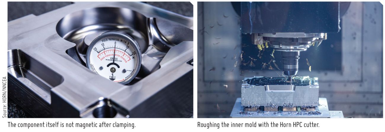
After face milling the external dimensions, the workpiece is clamped on fixed pole extensions. “The field line height, i.e. the depth of penetration of the magnetic field into the component, is around 10 mm at the maximum magnetic level. One concern about magnetic clamping is that the workpiece might remain magnetized after clamping. However, this is not the case. Due to the low penetration depth of the magnetic field, we have no problems with chips adhering to the surface even when milling the deep mold,” explains Weil.
|
The machining process was completed in four days of intensive cooperation. Different approaches were implemented to demonstrate the cost-effective processing of such a demanding component. |
For face milling of the outer surfaces, Horn’s DAH84 high-feed milling system was used. “The eight usable cutting edges of the indexable insert offer a low cutting price and high cost-effectiveness. Despite the negative installation position, the positive cutting edge geometry ensures a soft and quiet cut as well as good chip drainage,” explains Jenter.
The large radius on the main cutting edge of the insert creates a soft cut, ensures an even distribution of cutting forces and thus ensures a long service life. Surface finishing was carried out using the Type 409 tangential milling system.
Know-how in Programming
For roughing, Bangert used a function from the hyperMILL® MAXX Machining performance package. “In order to make the machining dynamic and efficient at the same time, I relied on 3D-optimized roughing. Machining is carried out in trochoidal tool paths and the milling cutter is immersed in the component via a helical ramp,” Bangert explains.
“It is particularly important that we can program a separate speed, the cutting speed, and a dwell time after immersion during immersion. This ensures a stable process throughout the entire process,” he adds.
The dwell time is necessary to give the spindle sufficient time to reach the correct speed so that the milling of the mold can start in trochoidal movements. The roughing of the mold is carried out as far as possible in a helix movement. This ensures that the tool is always gently cutting in sync without retraction movements and never engages in full cut.
To roughen the inner mold, Jenter relies on the Horn solid carbide end mills of the DS system. “We have developed HPC milling cutters especially for milling high-strength steels with a high metal removal rate,” he explains.
The system shows its strengths especially in dynamic roughing operations as well as in classic roughing cycles. For the first roughing operation, an HPC milling cutter with a diameter of 12 mm and four cutting edges was used. “Due to the contour, we did not choose a larger diameter to reduce the processing of residual material,” he adds.
The immersion angle is 5 degrees in a helix when retracting into the workpiece. The cutting depth is ap = 20 mm. The other cutting data are: vc = 140 m/min, fz = 0.08, and the lateral infeed ae = 3 mm.
The unequal twist angles and the resulting uneven tooth pitch enable very smooth running in use. The optimized face geometry of the tools reduces the cutting pressure when immersed in a helix or in the ramp. The improved chip spaces offer a high level of process reliability in chip forming and chip evacuation during operation.
For roughing the free-form surfaces, a high-feed milling cutter with a diameter of 12 mm is used. The milling cutters have a double radius geometry. This favors the flow of force in the axial direction of the spindle and low radial forces. “Thanks to this geometry, high feed rates can be applied even with long tool protrusions without vibrations occurring in the tool,” explains Jenter.
|
There are still reservations about magnetic workpiece clamping during milling, but the project demonstrated that this technology can be used and implemented reliably in production environments. |
TENDO E Compact Hydraulic Expansion Chuck
The roughing tools are clamped in SCHUNK Hydro expansion chucks. For roughing, Weil relies on the TENDO E compact series. The short design is well suited for machining. “I am often asked with what torque I have to tighten the feed. At SCHUNK, it’s very simple: All you have to do is turn the clamping screw all the way to the stop and this gives you the optimum concentricity and the best possible torque transmission of the tool,” describes Weil.
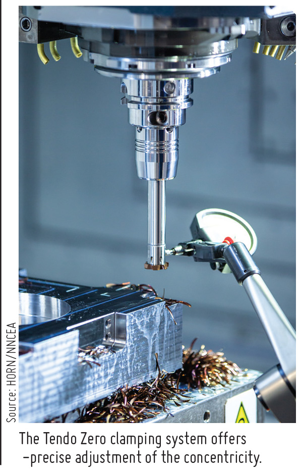
To accommodate the guide bolts of the later tool, four holes must be drilled at the corners of the workpiece. To clamp the reaming tools, Schunk relies on the TENDO Zero hydraulic expansion chuck. Four opposing Torx screws on the collar of the chuck allow the concentricity to be precisely adjusted. The user can measure the reaming tool on a presetting device and the final setting is then made directly in the machine using a dial gauge. This enables µ-precise adjustment of the concentricity. “With a clamping length of the reaming tool of over 100 mm, we have a concentricity of less than 2 µm. That's a very decent value,” says Weil.
High-performance DR Friction System
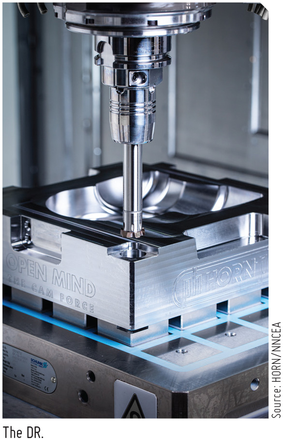
The reaming of the four bores was carried out by Horn’s DR friction system. With internal coolant supply, the cutting speed was vc = 110 m/min and a feed rate of 0.84 mm/rev. The retraction feed was programmed at 4000 mm/min. “It is important that no more than 2 mm emerge from the bore in the case of a long overhang length and a through hole. Otherwise, there is a risk of the tool swinging open,” explains Jenter.
The Horn friction system has a modular design and can be combined with numerous interfaces. The changing accuracy of the inserts is less than 4 µm. The system’s standard cutting edges can be used to machine materials up to a hardness of 58 HRC.
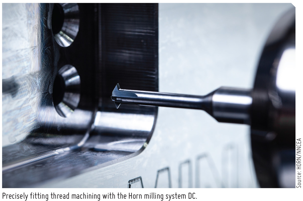
“We machined the four external threads with three lateral infeeds to ensure the exact fit of the thread. For machining, I used the hyperMILL® ‘thread milling’ function. This automatically calculates the value of the lateral infeed based on the tool and thread. The function supports both single-edged and multi-edged tools,” says the hyperMILL® expert.
The DC Horn thread milling cutter milled the threads at a cutting speed of vc = 80 m/min and a feed rate of fz = 0.02 mm/min. The tensioning system is not based on oil but on PU elements. This enables high vibration damping and thus a stable overall system for thread milling.
High Surface Quality Finishing
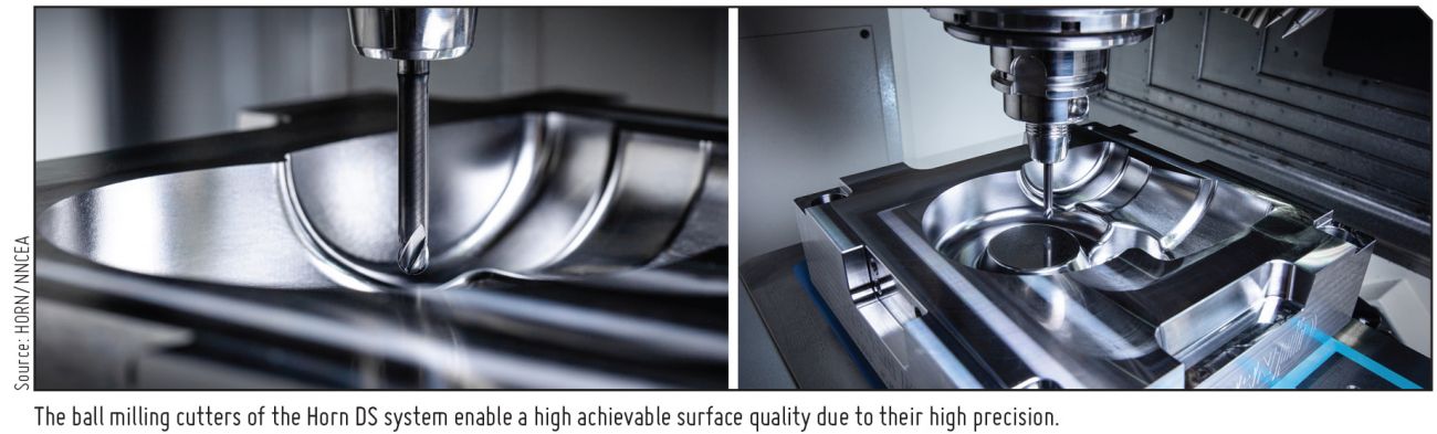
“When finishing a mold with different ball milling cutters, there are three crucial factors to achieve the required surface quality: the precision of the tool, a powerful CAM software for precise machining, and the accuracy of the clamping device. We manufacture the radii of the milling cutters with a maximum shape deviation of ±0.005 mm,” says Jenter. The importance of this precision can be seen when different milling cutters are applied to a shape to be finished.
Bangert programmed the mold with a 6 mm and a 4 mm ball milling cutter. “Before programming freeforms, we always check the requirements for the component first. These include, above all, the required surface qualities, the shape tolerances and the transitions during finishing,” he shares.
Machine kinematics and the interaction between clamping devices, tools, and machine control also play a decisive role.
For high-precision machining, the hyperMILL® CAM software already contains numerous strategies in the standard version. For example, the ‘High-precision surface mode’ option provides an increase in surface quality. This was also used in the machining of the mold.
Bangert explains: “The calculation of the tool paths takes place on the real CAD component surfaces and not on a calculation model. This allows tolerances in the µm range to be maintained. In addition, I used the ‘Soft Overlap’ function to grind the transitions between different surfaces, even if it was processed with a different tool or infeed. In this way, transition-free surfaces can be efficiently realized.”
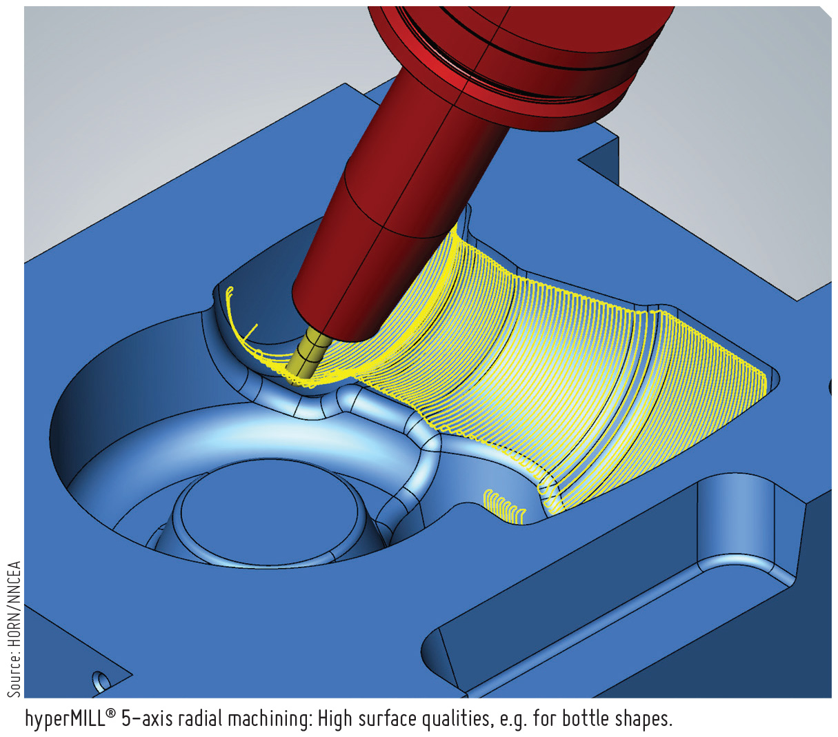
In addition, Bangert used the 5-axis radial machining function: “With this strategy, the best possible surface qualities can be achieved. A radial projection method allows tool paths for bottle shapes, for example, to be calculated much faster. In addition, the user is able to respond flexibly to the existing component conditions.”
|
When finishing a mold with different ball milling cutters, there are three crucial factors to achieve the required surface quality: the precision of the tool, a powerful CAM software for precise machining, and the accuracy of the clamping device. |
HORN in India
Precision Tooling Solutions for the Die & Mould Industry from Paul Horn GmbH are available in India via NN Combined Engineering Agencies Pvt Ltd (NNCEA) in cooperation with select OEM partners. NNCEA provides complete technical support, logistics and supply chain management solutions for the Indian market.
Source: NN Combined Engineering Agencies Pvt Ltd
 Facebook
 Linkedin
 Subscribe